Hydrogenation in Practice
The Author: Dr Rob F. Ariaansz
Introduction
The hydrogenation of fats and oils and their oleochemical derivatives such as fatty acids, fatty acid esters and fatty nitriles has proven to be a very useful and versatile way to modify these starting materials. This chapter will be limited to discussing exclusively the hydrogenation of carbon-carbon double bonds. Hydrogenation or the addition of hydrogen to the double bonds, allows the processor to modify the properties by removing (some of) the double bonds. He can do this to a limited but not unimportant extent, selectively. Selectivity is therefore another aspect used in fat modification by hydrogenation. The addition reaction of hydrogen to olefinic double bonds was discovered in the late nineteenth century by the French chemist and Nobel Prize winner Paul Sabatier [1]. He discovered that the reaction could be performed under relatively mild conditions in the presence of certain metals such as nickel, cobalt and platinum. He believed this could only be done with “volatile” organic compounds as the substrate. In the second half of the nineteenth century in many parts of Europe and later also in the USA (later followed by other countries), an increasing need emerged for low cost hard fats. These fats were needed for margarine manufacture and the replacement of butter of which there was a great shortage. The German chemist Wilhelm Normann was able to hydrogenate oleic acid to stearic acid with finely dispersed nickel, thereby disproving Sabatier’s limitation to “volatile” organic compounds. This led to several patents [2] granted to Normann, covering the hydrogenation of “unsaturated fatty acids and their glycerides”. From about 1909 the hydrogenation of triglycerides became an increasingly popular process in Western Europe and in the USA. Soon it was applied by many companies all over the world as a relatively low-cost and versatile source of stable oils and fats, using locally available liquid feedstocks.
Purpose of hydrogenation
In general, hydrogenation serves any or several of the following purposes:
-
- To convert a liquid oil into a solid fat.
When solid fats of the right consistency are expensive or not available, hydrogenation, sometimes in combination with other processes such as interesterification or fractionation, may provide a way to produce the desired fat. - To change the consistency of a fat.
The melting point of a hydrogenated fat can be controlled by the degree of hydrogenation. Vegetable oils contain practically exclusively cis isomers of fatty acids. Hydrogenation will also convert some of the cis isomers into trans isomers, which give the triglycerides different melting characteristics. Furthermore, by using specific catalysts and/or hydrogenation conditions (such as temperature and hydrogen pressure), the composition of the fatty acids and the level of cis and trans isomers occurring at a particular iodine value (IV) can be controlled. Consequently, the melting behaviour of the fat at a particular IV can be influenced by the processor. - To stabilise an oil or a fat.
In general, saturated fatty acids are chemically more stable than unsaturated fatty acids. By converting unsaturated fatty acids to less unsaturated ones, the shelf life of the product will be improved and also the product may become more suitable for heavy-duty functions, such as frying. - To broaden the availability of edible oils and fats. Whale oil and later fish oil are too ‘fishy’ for consumption. By hydrogenating these oils, palatable hardstocks were made available.
- To convert a liquid oil into a solid fat.
Requirements for hydrogenation: raw materials, equipment, analytics
3.1. Raw materials
3.1.1. The oil.
The catalyst used for the hydrogenation is sensitive to various contaminants that may be present in the oil. These contaminants may either decrease the activity of the catalyst reversibly or poison the catalyst permanently. When the catalyst is poisoned, its change cannot be reversed and it must be replaced by fresh catalyst. This means that the oil should be refined to such low residual levels of contaminants that the catalyst consumption is reduced to an economically acceptable level. Generally, (apart from other choices made in refining) the choice in favour of more thorough refining with consequently lower catalyst consumption and better predictable catalyst performance, has to be weighed against its higher costs. The level of the individual contaminants varies for each type of oil. The choice on which contaminant to focus in refining will therefore differ for each type of oil. Hence it is impossible to give general guidelines for the desired purity covering all types of oils but it is good practice to try and attain the following levels of some common potential contaminants:
Acidity: < 0.1 % free fatty acids by weight
Sulphur: 5 mg/kg max.
Phosphorus: 5 mg/kg max.
Moisture: < 0.05 % by weight
Soap: < 0,05 % by weight
Oxidation products: peroxide value = 0 (meq/kg), p-anisidine value < 5
3.1.2. The hydrogen.
Hydrogen may be obtained from various sources: bottled hydrogen or supply by pipeline from a major producer of gasses, electrolysis (usually on site) or gas reforming (usually on site). The designer of the hydrogenation plant is supposed to know what quality the hydrogen should have. The quality of the hydrogen is therefore rarely an issue. Hydrogen can contain three groups of contaminants which may affect the hydrogenation: inerts, inhibitors and poisons.
Inerts are other gasses than hydrogen, such as methane, water or nitrogen which lower the partial pressure of the hydrogen, thus reducing the rate of the hydrogenation. This is particularly problematic in batch hydrogenation because as the hydrogen is being consumed during the hydrogenation, the inerts accumulate in the headspace of the reactor. As the total pressure is usually kept constant, the partial pressure of the hydrogen will therefore decrease.
Inhibitors are substances that temporarily interact with the catalyst and lower its activity. When conditions change and desorption takes place, the original catalyst activity is restored. An example would be carbon monoxide. A catalyst poison is a substance that reacts with the catalyst and that affects its performance in an irreversible manner. The most common type of poison occurring in hydrogen are sulphur containing gases.
Below the levels of contaminants in hydrogen gas are specified:
Sulphur: < 200 mg/kg
Inerts: < 0.2 % by volume
Moisture: < 0.1 % by volume
Carbon monoxide: < 0.03 %
3.1.3. The catalyst.
In the hydrogenation of fats and oils the only catalysts used industrially are the so-called supported nickel catalysts (see also 3.2.1.1.), whereby the nickel metal is mounted on an inert support material.
In the past, other catalysts have also been used, e.g. Ni-formate, Raney-type nickel, nickel-copper and copper-chrome. In addition, the use of precious metal (supported palladium and platinum) catalysts has been explored.
Ni-formate and Raney-type catalysts needed to be activated in situ. They were in use until the 1940s and 1950s, when pre-reduced supported Ni-catalysts that were easy to handle, became generally available. The current supported Ni-catalysts are vastly superior in performance to Ni-formate and Raney-types.
Ni/Cu was much in use in the former Soviet Union countries. These catalysts were more active than Ni-formate but they had to be activated in situ at relatively high temperatures (> 210 °C).
In the 1970s some companies experimented with Cu/Cr-catalysts [3]. The active component is the copper. It was thought that they might offer the advantage of having a very high linoleic acid selectivity (see 5.1.) but their use was short lived because Cu (a very strong pro-oxidant) was difficult to remove, their low activity made them expensive and the presence of Cr6+ made safe handling of the powdered catalyst problematic.
During the early part of this century, processors took a serious look at precious metal catalysts because they might help to suppress the level of trans isomers in partially hydrogenated products. This could only be achieved to a limited extent and trials were soon abandoned due to the overall cost of these catalysts vs. Ni.
The supported Ni-catalysts used industrially for slurry phase processes consist of extremely finely dispersed nickel on an inert support that is suspended in a protective medium. The nickel has been pre-reduced, usually with hydrogen at high temperatures (300 - > 400 °C). It is present as very small crystallites to create a high surface area (up to c. 100 m2/g Ni), which results in a high activity. Along with a high surface area, the Ni must also be well accessible. In order for the catalyst to be filtered with relative ease, the Ni is deposited on a porous support powder (e.g. alumina or silica) with good filtration properties. Due to its high surface area, the Ni is very pyrophoric so for ease of use it has to be protected by means of a coating, typically a fully hardened edible oil. In the catalyst production process, the reduced catalyst is mixed with molten coating fat, the resulting suspension is then cooled down and allowed to solidify in the form of ‘droplets’ or pellets. In the hydrogenation plant of the catalyst user, the droplets are put in hot oil, the coating fat melts and the catalyst particles are subsequently released into the oil that is to be hydrogenated. There are several technical criteria that play a role in the characterisation of a catalyst:
-
- The activity. Obviously, the activity should be high because it not only determines the time needed to hydrogenate a batch of oil (production capacity) but also it determines to a great extent how much catalyst must be added to achieve a reasonable batch time (i.e. catalyst cost related). See also section 4.
- The resistance against deactivation, the so-called ‘poison resistance’.
This property only plays an important role if the feedstock contains relatively high amounts of contaminants that could deactivate the catalyst or if the catalyst is re-used many times so that catalyst poisons build up as the catalyst is reused. See also 5.2. and 5.3. - The selectivity. In those cases where the feedstock is partially hydrogenated, selectivity always plays a role of some importance. It describes e.g. to which extent the catalyst has a preference to hydrogenate polyunsaturated fatty acids over monounsaturated fatty acids and whether it produces higher or lower amounts of trans-isomers than other catalysts. See also Hydrogenation Mechanism.
The selectivity influences the melting characteristics and the stability of the hydrogenated fat. - The filtration properties. Generally, a plant should be designed to filter any type of catalyst available on the market but plant modifications such as capacity increase realised at a later stage, sometimes result in filtration becoming a critical item. In a batch-type of operation, filtration should be fast enough to enable to start the next filtration cycle as soon as hydrogenation of the next batch of oil is finished. Looking for even faster filtration is of no relevance. The time to filter a batch of oil depends on many factors, one of which is the particle size and particle size distribution of the catalyst. See also section 4.
3.2. Equipment.
3.2.1. The reactor.
3.2.1.1. Batch autoclaves.
In general, the autoclave is provided with two upstream pieces of equipment that prepare the oil for the hydrogenation: heating equipment and drying equipment. The catalyst has a minimum temperature at which it will become active. Usually this ‘light-off’ temperature is higher than the temperature of the oil coming from storage. Hydrogenation is an exothermic process so for reasons of heat-efficiency, the incoming oil is generally heated up in a heat exchanger, using the exothermic heat generated by the previous batch of hydrogenated oil. In order to make sure that the oil is dry enough, the incoming oil is either dried prior to or after entering into the autoclave.
In the batch process, the oil is filled into the autoclave, oxygen is removed by evacuating the reactor several times, the oil is hydrogenated, then drained form the autoclave, usually into an intermediate vessel (drop tank), from where it is sent to filtration to remove the catalyst. As soon as the autoclave is emptied, it can be filled with the next batch of oil.
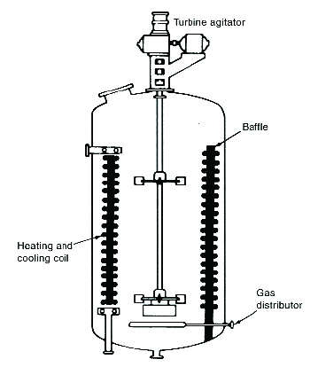
The autoclave has to ensure that the hydrogen is dissolved efficiently into the oil. The conventional type of autoclave is a stirred tank, in which the hydrogen is introduced through a sparger ring at the bottom of the tank (see figure 1). The hydrogen bubbles are dispersed into tiny bubbles by means of a central vertical agitator device. Baffles are attached to the internal wall of the autoclave, and cooling and heating coils are fitted as well. The baffles ensure that the oil does not swirl around without achieving much mixing with the gas bubbles and the catalyst. Once the undissolved H2 gas bubbles have reached the headspace of the autoclave, the rate at which the H2 can be made to dissolve in the oil becomes much lower because the H2 can only enter into the oil at the upper surface.
Figure 1. Conventional batch reactor [4]
More advanced types of autoclaves are equipped with ways to re-introduce the H2 into the oil, e.g. by pumping it back into the oil through an external pump. Another widely used system has a hollow agitator shaft through which the H2 is sucked down by means of a vacuum, generated in the lower part of the agitator, where the gas is re-introduced into the oil (e.g., the Ekato hydrogenation reactor: https://www.ekato.com/en/products/process-plants/hydrogenation-plants/hydrogenation-reactor/).
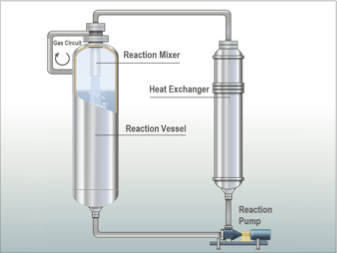
In another type of (generally) batch autoclave, the reaction mixture (oil, H2 and catalyst) is continuously re-circulated by an external pump through an external heat exchanger and a venturi jet that is located inside the autoclave, where fresh H2 is added (see figure 2). These reactors are generally referred to as ‘loop-reactors’ (e.g. manufactured by Buss ChemTech and others). They are expensive but very efficient, thanks to the highly intimate mixing of gas and liquid in the venturi jet.
Figure 2. Loop reactor (image courtesy ©Buss ChemTech https://www.buss-ct.com/buss_loop_reactor.html)
3.2.1.2. Continuous reactors.
Particularly in the oleochemical industry, there are several plants that run in a continuous way while using powdered catalysts (i.e. same type as mentioned in 3.2.1.1., supplied as fat coated droplets). These reactors are essentially a vertical reactor tube in which the catalyst/feedstock mixture flows downward and into which hydrogen is injected at different stages. For fatty acid hydrogenation this works well but these reactors are less suited for triglyceride oils than the so-called fixed bed reactors.
Fixed bed reactors are very common in the chemical and in the petroleum industry but are surprisingly rare in the fats and oils industry. They basically consist of a cylindrical, vertically mounted reactor which contains a bed of catalyst in the form of extrudates or tablets, supported by a grid at the bottom of the reactor. The best way to operate such a reactor is in “trickle phase downflow” mode. The feedstock goes through a distributer plate on top of the catalyst bed, which distributes the liquid evenly over the bed. By design, the flow of liquid is limited in such a way that the liquid trickles down through the bed while coating the catalyst particles with a thin layer. This allows the hydrogen, also entering from the top and occupying the void spaces between the catalyst particles, to dissolve into the liquid effectively. Consequently, the hydrogen concentration in the oil is higher than in the commonly used dead-end batch autoclave. In addition, the residence time of the triglycerides inside the catalyst particles (being much larger than the particles used in batch autoclaves) is much longer. As a result of both factors, the linoleic acid selectivity is reduced so that much more saturated fatty acids are formed. When the catalyst is fresh, most of the exothermic heat will be generated in the top section of the reactor. This can lead to excessive local heating. To prevent this from happening, hydrogen flow must be sufficiently high. When the aim is to fully hydrogenate a relatively unsaturated oil, special measures must be taken to remove the heat of reaction. This can be done by recirculating part of the product leaving the reactor, thus diluting the feedstock. Another way of controlling excessive reaction heat is to use a tubular reactor, containing many (often > 1000) tubes, filled with catalyst and immersed in a cooling medium.
The advantages of fixed bed vs. batch hardening are:
-
-
- Low investment cost
- Low running costs
- Large production volumes are easily achievable
- No filtration needed
- 24x7 hr. production with a high level of automation and little supervision
- Uniform product
- Long catalyst life: a life of 5 years is no exception
- Infrequent spent catalyst handling, often outsourced to specialised companies
There are also disadvantages:
-
- Selective (partial) hydrogenation not possible, but quite suitable for full hydrogenation
- Unsuited for frequent feedstock or product changes because there will always be a considerable changeover volume
- Frequent shut-downs and start-ups are not very practicable
- Unsuitable for contaminated feedstocks
-
3.2.1.3. Other types of reactors
Over the years other types of reactors have been designed and tested. As none of them are currently in use, it suffices only to mention them.
Examples are: the use of solvents (e.g. in a supercritical state [5]), or electrochemical reactors [6], catalyst membranes or monoliths and ultrasonic equipment.
Hydrogenation in practice
The following is a general description of a typical hydrogenation run in a batch autoclave (see figure 3.).
Figure 3.
The neutralised and bleached – some operators use neutralised, non-bleached oil - feedstock is pumped into the autoclave to the level suggested by the designer of the autoclave. A higher or a lower level may result in a less than optimal mixing of oil, gas and catalyst.
The oil is either dried by means of a vacuum device prior to entering into the autoclave or it is done in situ after or during heating of the oil to the required starting temperature of the hydrogenation (e.g. 140 °C). High moisture levels of the oil tend to cause hydrolysis during the hydrogenation process, causing unacceptably high free fatty acid (ffa) levels of the hydrogenated product. The formation of free fatty acids is strongly temperature and time dependent so a low moisture level of the starting oil is particularly important at high hydrogenation temperatures (180 – 200 °C). Free fatty acids poison Ni-catalysts. They will irreparably damage the catalyst in a short time (even in 10 – 20 minutes) by causing Ni-soaps to be formed, which need to be removed after the hydrogenation. By evacuating the autoclave, the operator also makes sure that most oxygen is removed before hydrogen is allowed to enter the autoclave.
The catalyst is either added directly into the autoclave (preferred but less common because it is not easy to achieve) or as a concentrated suspension, prepared in a separated “slurry tank”. When the latter is used, the catalyst is mixed with fresh oil at about 100 °C. It is important that the addition of the catalyst and the way the tank is agitated, does not allow molten catalyst droplets to settle at the bottom of the tank. These molten droplets may not easily go into suspension. This could also happen when the temperature is not high enough. It is also important to note that the catalyst slurry tank generally does not offer the best storage conditions to the catalyst: the feedstock may not be dry and also the tank is generally not nitrogen blanketed so the catalyst may be subjected to some oxidation. For these reasons, it is recommended that the catalyst pre-mix be prepared as shortly as possible before the oil in the autoclave is ready to receive the catalyst.
The activity of the catalyst is temperature dependent. The higher the temperature, the more active the catalyst will be. Although there are differences between catalysts, for practical purposes it is advisable to ensure a reasonable activity at the start of the reaction. Therefore 130 – 150 °C is a common temperature to start the reaction. For certain oils (e.g. castor oil) and for certain hydrogenation purposes (trans-supressing hydrogenation) it may be necessary to exploit the ability of Ni-catalysts to hydrogenate at much lower temperatures. However, slight surface oxidation of the Ni crystallites may reduce the ability to hydrogenate at low temperatures. Although in the production of Ni-catalysts high temperatures are required to reduce the Ni from its oxidised state, slight surface Ni oxidation can be reduced at much lower temperatures, typically around 150 °C and higher. When very low hydrogenation temperatures need to be used, one should use fresh catalyst but it may be necessary to “pre-treat” the fresh catalyst with hydrogen at 130 – 150 °C to remove the surface oxidation. When the latter is removed, Ni-catalysts are able to hydrogenate at temperatures of as low as 90 – 100 °C.
Once the reaction catches on, the heat added by the heating coils and by the exothermicity of the reaction, will soon cause the batch temperature to reach its desired level. Even shortly before that point is reached, it may be necessary to start cooling in order not to overshoot the target temperature.
At the early stages, the impact of the hydrogen pressure on the selectivity is limited because the high reactivity of catalyst and oil, resulting from the high concentration of double bonds, will the keep the concentration of the hydrogen in the oil very low. During the first stage of the reaction it may therefore be helpful in reaching a steady state situation by raising the hydrogen pressure to a higher level than is required according to the usual procedure. Obviously, when selectivity is not an issue (e.g. for full hydrogenation), a high pressure will result in either shorter batch times or in lower catalyst concentrations needed to reach the end point in an acceptable period of time.
When the “steady state situation” is reached, it will become clear that the reaction gradually slows down. There are three reasons for this. First of all, the concentration of double bonds decreases in the course of the hydrogenation, causing the kinetics of the reaction to slow down. Secondly, the selectivity of the reaction causes the polyunsaturated fatty acids to react first so that the less reactive monounsaturated fatty acids become more predominant and thirdly, the catalyst loses activity due to crystallite growth (loss of metal surface area) and the effect of catalyst poisons.
The end point of the hydrogenation is determined either by analysing samples taken during the run or by following the level of saturation of the double bonds. The latter can be calculated from the hydrogen consumption, adjusted for the amount of hydrogen that has ended up in the headspace of the autoclave. Another way to determine the degree of hydrogenation is to determine the IV of the oil in the autoclave. This can be done off-line by analysing samples or on-line by a special device connected to the autoclave, based on infra-red readings.
It is important to realise that when the supply of hydrogen is switched off, the hydrogen present in the oil and in the headspace may continue to react. Experience will tell how much earlier than reaching the desired end point the hydrogen supply should be switched off to prevent overshooting the end point.
After deciding on a hydrogenation procedure based on previous experience, the first trials can start. Large scale hydrogenation usually begins on a small scale, i.e. in a laboratory reactor or pilot plant reactor. When a suitable catalyst and suitable conditions have been selected by means of a number of small-scale trials, the recipe would then be scaled-up to plant scale. When no previous commercial scale experience with the reactor in question exists, this often leads to surprises. The operator would typically discover that the hydrogenation in his plant equipment is much slower than in the laboratory and that the product has different properties because the selectivity that occurred in the partially hydrogenated product is different from the one made in the laboratory. Three main reasons can be identified:
-
-
-
- The temperature effect.
Most laboratory reactors are designed to work isothermally, whereas in an industrial batch autoclave one would start the reaction at the lowest practicable temperature. After some time, the desired reaction temperature will be reached. The changing temperature will have an effect on both the rate of the reaction and the selectivity (in the case of partial hydrogenation), which causes the result to be different from what is obtained in the laboratory under isothermal conditions, in terms of reaction time and product properties.
By using data from previous runs, it is possible to simulate a temperature effect in the laboratory reactor, ideally by programming a temperature increase during the first part of the reaction or by carrying the reaction out in two stages: first at a reduced temperature, then at the desired reaction temperature. - The effect of the pressure.
Generally, laboratory reactors are run at constant pressure. In “real life” things are usually different. When the reaction starts, the temperature is still relatively low and the rate of the reaction is accordingly low as well. Therefore, the rate of consumption of hydrogen is also low. In most reactors this means that a lot of hydrogen will bubble through the oil to the head space of the reactor and the pressure will build up to the set level. When the rate of the reaction picks up, most reactors will not be able to replenish all of the consumed hydrogen and the pressure in the head space will start to drop. At a later stage of the reaction, the consumption of hydrogen will drop due to reduction of the concentration of double bonds in the substrate and due to catalyst deactivation. This will cause the pressure to rise again to the set level.
Also the pressure has an effect on the rate of the reaction and on the selectivity, causing the plant results to be different from the one obtained in the laboratory. Based on historical plant data, simulation can be done in the laboratory in a similar way as described for the temperature effect. - The third reason why hydrogenation in the plant may turn out to be very different from the trials in the laboratory is due to the difference that mostly exists in the mixing efficiency of the reactors.
The rate at which hydrogen is dissolved into the oil (e.g. in Nm3 H2/m3 oil/s) is described by the following equation:
rH = kL . a . ([H2]0 - [H2]), whereby:
kL is the liquid-side mass-transfer coefficient (m/s) in the stagnant layer of liquid surrounding the gas bubbles.
a is the specific interfacial area (m2/m3oil), separating the oil from the gas in the bubbles and the head space of the autoclave. “a” depends primarily on reactor design.
[H2]0 is the hydrogen concentration (mol/m3) in the gas-oil interface (i.e. the solubility of hydrogen in the oil under the reaction conditions).
[H2] is the actual concentration of hydrogen (mol/m3) in the bulk oil.
In industrial autoclaves kL.a values differ widely, mostly from 0.05 up to > 0.5 in very efficient reactors. Many types of laboratory reactors on the other hand can reach values of > 2.0, thanks to their much higher agitation energy input. The maximum rate which a reactor can approach to satisfy the [H2] hunger caused by the reaction kinetics is [7]:
rH (max) = kL.a . [H2]0
This theoretical maximum hydrogenation capacity situation is getting close to being reached when practically all of the hydrogen entering the oil reacts away immediately (i.e. [H2] is approaching zero). Of course [H2] = 0 will never be reached because there will always be a concentration gradient between the oil surrounding a H2 bubble and the oil surrounding a catalyst particle.
In other words: no matter how active a catalyst is or no matter how much catalyst is added, there is a limit to the “observed overall rate of the reaction” that an autoclave is able to approach under maximum production conditions. To put it in business terms: there is a limit to the production capacity of the hydrogenation unit, which is entirely determined by the mixing efficiency of the autoclave.
As a crude approximation, the relationship between the observed rate of the reaction (robs., e.g. in Nm3 of H2 consumed per m3 oil per sec.), the maximum theoretical production rate the reactor is able to approach (rm, expressed in the same units), the rate purely determined by the kinetic rate of the reaction (rkin ), the catalyst concentration needed to neutralise catalyst poisons (cpois.) and the catalyst concentration needed to perform the hydrogenation reaction ccat.), can be expressed by the following equation (note that “rkin” has different units than robs. and rm ):
Imagine a series of experiments in which the catalyst concentration is increased stepwise. When we look at what happens to the “observed rate of the reaction”, we see that at the beginning (at very low concentrations of catalyst) no reaction takes place because all of the catalyst is deactivated by the contaminants in the feedstock. As the concentration of the catalyst is increased, there comes a point at which all contaminants are neutralised by the catalyst and at which point any further increase will result in an increasingly faster (observed) hydrogenation reaction. From this point onwards, robs. will first follow the catalyst concentration in an almost linear way. At higher dosage levels of catalyst however, the curve will level off, to finally approach the theoretical maximum rate of the reaction (rm), which is a characteristic of the design of the reactor in question. Beyond that point no appreciable further changes to the observed rate of the reaction will occur when more catalyst is dosed or even when a more active catalyst is used.
In their development facilities, catalyst manufacturers generally use autoclaves that permit fast hydrogen dissolution so that they have a wide window to operate in the linear concentration dependency range, which helps them to determine differences in the intrinsic activity of different catalysts. For them this is useful for both quality control (batch to batch variability) as well as for R&D purposes.
Industrial users of catalysts benefit more from laboratory reactors that are able to mimic their production autoclaves more closely. Reducing the agitation speed of a high-efficiency laboratory reactor to match production rates is generally not the best solution. Typical laboratory autoclaves are designed only for a limited range of the agitation speed. At lower speeds, gas/liquid mixing may drop steeply or the catalyst may even start to settle to the bottom of the autoclave. The job of fine-tuning laboratory and pilot plant mixing efficiency to match the performance of the plant reactor therefore begins with using the same catalyst concentration in the laboratory as is used in the plant so that poisoning effects are the same. For further fine-tuning it is advisable to stay on the safe side (the lower end) of the agitation range. When a further reduction of the reaction rate in the laboratory autoclave is needed, it is best achieved by lowering the pressure used in the experiments in the laboratory autoclave so that the catalyst is facing a similar hydrogen concentration as in the plant. When enough correlations between laboratory and plant runs have been provided, one can predict fairly accurately how to translate the lower pressure in lab experiments to the higher pressure needed in the industrial autoclave to achieve the same result in terms of reaction time, selectivity and required catalyst concentration.
- The temperature effect.
-
-
After the hydrogenation, the product will generally be drained from the autoclave through a heat exchanger into a drop tank. It is good practice to either use a vacuum or fill the empty space in the drop tank with nitrogen because there can still be some hydrogen adsorbed on the catalyst or dissolved in the oil. Contact with air should be avoided.
The next step in the production is removal of the catalyst by means of filtration.
There are several types of filters that can be used to remove the catalyst [8].
For a long time, open filter presses of the plate-and-frame type have been used. In many plants this type is still in use. Mostly, operators have to drop the filter cake manually. This practice is now generally seen as irresponsible, unless operators are protected by means of dust-tight clothing and clamshell helmet with breathing equipment. The reason is that when the fat content of the filter cake is reaching a low level, the cake can become dusty. Catalyst dust can easily oxidise and form exposed nickel oxide. Nickel oxide is a compound that constitutes a serious health hazard. Handling of non-dusty filter cakes on the other hand, is safe. As a general indication, filter cakes may start to get brittle and dusty when their fat content is lower than about 30 % by weight.
Today, the filter types of choice are closed filter systems such as metal gauze filters and candle filters.
Metal gauze filters (pressure leaf filters) consist of a tank which can be pressurised, in which either vertical or horizontal filter leaves are mounted. By pressurising the oil/catalyst suspension (the reaction mixture coming from the reactor) inside the tank, the suspension is forced to pass the leaves from the outside in. The filter leaves have metal gauzes on both sides of the leaf which retain the catalyst particles and which drain the oil from the inside of the leaves through a manifold which is connected to the drain pipe of the tank, leading to the filtered oil tank. The weave of the leaves typically has apertures of around 80 µ and this is generally too coarse to retain the catalyst particles of mostly 5 – 10 µ average size. It is therefore necessary to use a filter aid, either as a precoat or as a body feed. The filter aid is much coarser than the catalyst and it will leave a coating layer on the filter leaves on to which the catalyst cake will build up. The filter cake can be dropped from the leaves through a butterfly valve at the bottom of the tank. The advantage of such a system is that it is closed and that it can be fully automated.
The same is true for the candle type of filter system which is getting more and more popular today. This type of filter comprises a pressurised tank, in which a series of candles are mounted. Each candle is covered by a cloth on which the filter cake builds up. The filtered oil is drained from the inside of the candles. The cloths are woven sufficiently tight to retain the catalyst particles so filter aid is generally not required. Release of the cake at the end of the filtration cycle is effected by means of a nitrogen pressure shock, which blows the cloths outwards from the centre, thus breaking the filter cake.
The usual oil temperature range for catalyst filtration is 100 – 140 °C. Too low a temperature can result in slow filtration due to the higher viscosity of the oil and even to solidification of the fat in external draining pipes. Too high a temperature may cause nickel soap formation or deterioration of the fat. High temperatures may also not be compatible with certain synthetic cloth materials.
As said, the filter cake may be dry and brittle when the fat content is low, causing oxidation of the nickel, which is a very exothermic reaction. In some cases, these high temperatures have been known to ignite the fat, causing smouldering or even burning of the filter cake. It is therefore good practice that when there is a suspicion that the filter cake may be too dry, to spray water on top of the cake released from the filters in order to prevent access of oxygen. The spent catalyst is purchased by specialised companies who reclaim the metal from the catalyst.
A polishing filter is installed downstream of the main filter. This can be either a bag filter or a cartridge filter, both of which normally need to be serviced (i.e. replacement of the bag or cartridge) only once in a while.
The hydrogenated oil is not completely free of nickel at this point. In most instances a few ppm of nickel (ranging from < 1 – 10 mg/kg) can still be found in the oil. In some countries there is a legislative limit on the level of nickel in edible oils and fats. In any case, for consumer safety it is common practice to reduce the level of nickel to < 0.2 mg/kg. This residual nickel is partially present in the form of particulate nickel, partially as nickel soaps. The particulate nickel consists of sub-micron catalyst particles that originate from abrasion of catalyst particles and that are too small to be caught in the main filter. In principle, they can be removed in the polishing filter. The portion of residual nickel which is in the form of nickel soaps, originates from the reaction of free fatty acids with the catalyst. The nickel soaps are generally soluble in the oil and hence they cannot be removed as such by means of filtration. The way to remove them is to add a compound with which they form an insoluble complex, e.g. citric acid, sometimes phosphoric acid. Addition of 0.01 – 0.05 w/w % of a 50 % aqueous solution of citric acid should suffice. Due to the small amount and the particle size of the nickel complex formed, it will be necessary to add either filter aid or bleaching clay as a vehicle to “carry” the complex in the final filtration step. The resulting filter cake needs to be disposed of as nickel containing waste.
Some companies prefer to post-bleach and deodorise the hydrogenated product prior to further processing and blending with other oils or fats.
Various practical aspects of hydrogenation
5.1. Influence of process conditions on selectivity.
As pointed out by Dijkstra in the chapter “Hydrogenation Mechanism”, we only have to consider two types of selectivity: linole(n)ic selectivity (also referred to as “preferential selectivity”) and trans selectivity [9].
Both are influenced by the catalyst, catalyst poisons, degree of saturation of the oil and by the hydrogenation conditions. Taking some short cuts through the intricate maze of reactions taking place when studying the hydrogenation mechanism in detail, for practical purposes the following trends can be observed:
a. Particularly when the catalyst is fresh, part of the hydrogenation take place on the outside of the catalyst particles. However, it can be assumed that more hydrogenation takes place inside the pores of the catalyst, since these contain by far the largest catalytic surface.
b. As most of the unsaturated molecules have to diffuse into the pores before they can react, the overall rate of the reaction partially depends on the length and the width of the pores. Narrow pores reduce access to the catalytic surface and reduce the reactivity. The intra-pore diffusion of the much smaller H2 molecule will be less hampered than that of the triglyceride molecules, resulting in a higher H2 concentration. In addition, once a molecule gets “trapped” inside a (narrow) pore, it runs a greater chance of being hydrogenated more than once before it returns to the bulk oil. Catalysts with narrow pores and those with large particles will therefore tend to form more stearyl glyceride and to have a lower linoleic acid selectivity.
c. In principle, all hydrogenation catalysts encourage a move towards the thermodynamic equilibrium between cis- and trans-isomers, which at 170 °C lies at about 25 % cis and 75 % trans. This high level of trans-isomers is in practice never reached, unless it is specifically targeted, e.g. by sulphiding the catalyst and by pushing on until the 70 – 75 % trans is approached.
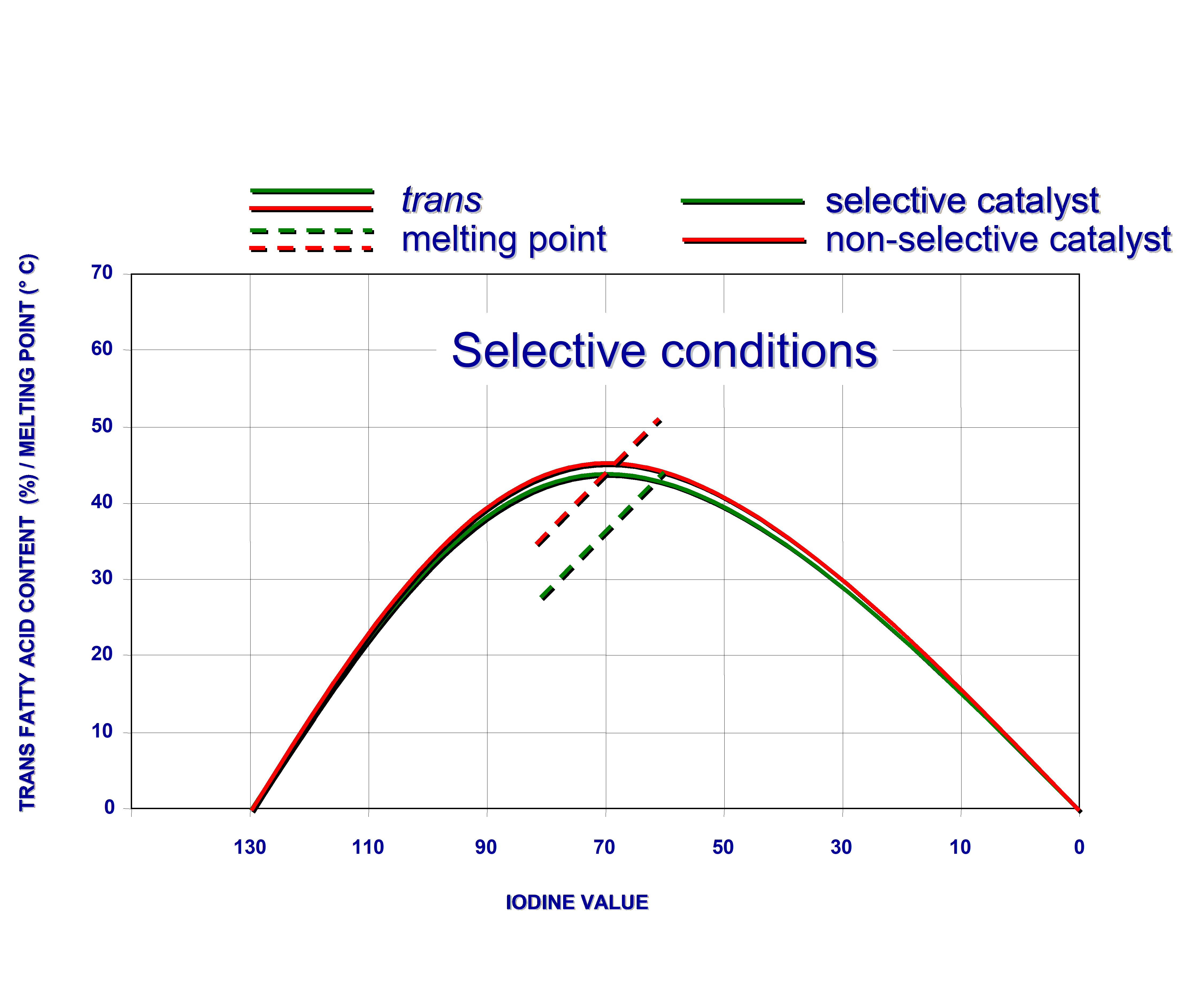
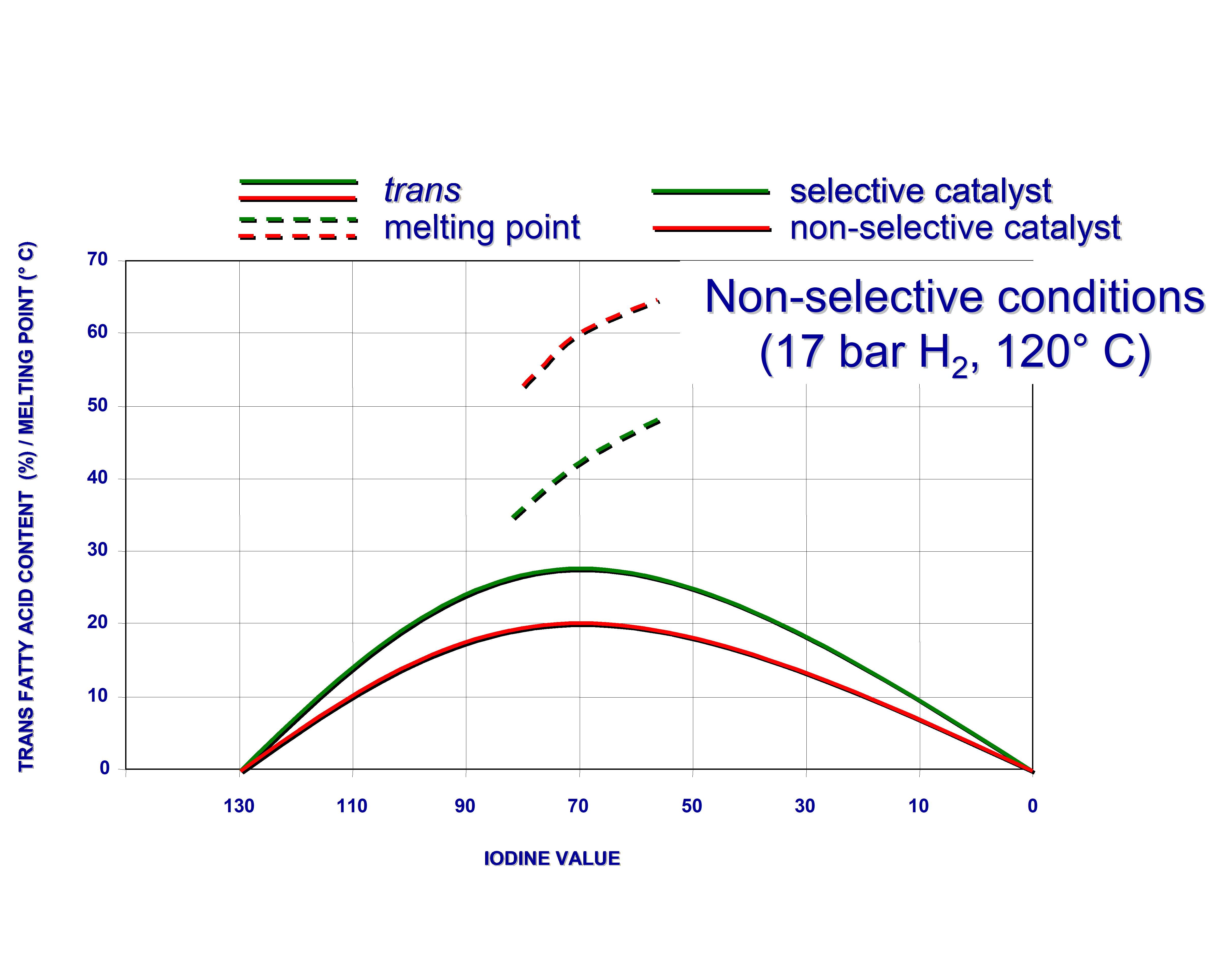
Fats, hydrogenated with different non-poisoned nickel catalysts to the same IV, can still have different trans-isomer contents. This is a secondary effect of the selectivity. So-called “unselective catalysts” yield, at the same IV, a fat with both more saturated fatty acids and more non-hydrogenated (including polyunsaturated) molecules than their selective counterparts. As fully hydrogenated molecules have no cis or trans isomers and since the double bonds in molecules untouched by the catalyst, are still in the cis configuration, unselective catalysts “produce less trans”. This effect is even greater when comparing fats of the same melting point because the unselectively hardened product will have a higher IV than the selectively hardened fat with the same melting point.
This is illustrated by figure 4 below.
Figure 4. Hydrogenation of soyabean oil under selective and non-selective conditions
d. The (net) supply of hydrogen to the catalyst can be increased in several ways, for instance by increasing the pressure or by improving the gas-liquid mixing. The hydrogen concentration on the catalyst surface will also increase when the demand of hydrogen is lower. This is the case when the hydrogenation is carried out at a lower temperature (thus slowing down the reaction) and also, by default, as the hydrogenation run progresses and the concentration of unsaturated bonds decreases. On the other hand, highly unsaturated oils will cause a higher demand of hydrogen, resulting in the hydrogen concentration on the catalyst to be lower than during the hydrogenation of less saturated oils. In accordance with the mechanism described by Dijkstra, a higher concentration of hydrogen on the nickel surface results in a lower linoleic acid selectivity (best expressed as the ratio of the reaction rates Slinoleic = rlinoleic/roleic) because the rate of the saturation of the monoene is more strongly dependent on the hydrogen concentration than that of the diene. The effect of a greater abundancy of hydrogen on the cis/trans isomerisation is that the half-hydrogenated intermediate reacts further (with a second hydrogen atom) more rapidly. Therefore fewer bonds of the half-hydrogenated intermediates will rotate around the original double bond and form potential trans isomers.
e. The effect of the temperature is primarily that at higher temperatures the rate constants of the hydrogenation reactions are higher, causing higher consumption of hydrogen. With a greater scarcity of hydrogen on the catalyst surface, the opposite consequences to those of the increase of hydrogen supply will occur.
The effects of process conditions and feedstock unsaturation on selectivity are summarised in the table below [10]:
| Increase of Process Parameter | Effect on H2 supply | H2 concentration on Ni | Preferential selectivity | cis/trans isomerisation | ||||
|
Pressure |
Larger supply of hydrogen | + | - | - | ||||
|
Agitation |
|
+ | - | - | ||||
| Catalyst Concentration | Larger demand for hydrogen | - | + | + | ||||
| Temperature | - | + | + | |||||
| Catalyst activity | _ | + | + | |||||
| Degree of oil unsaturation | _ | + | + |
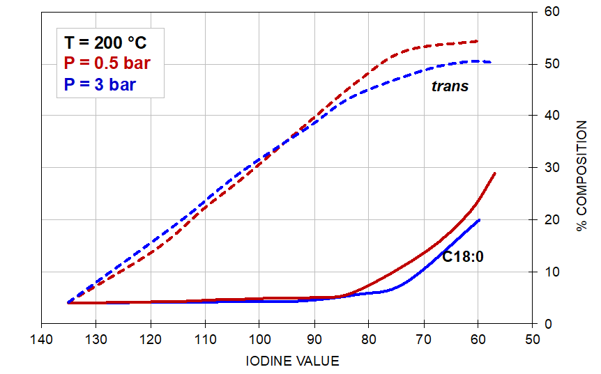
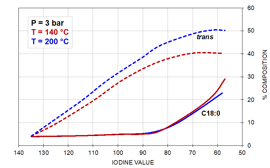
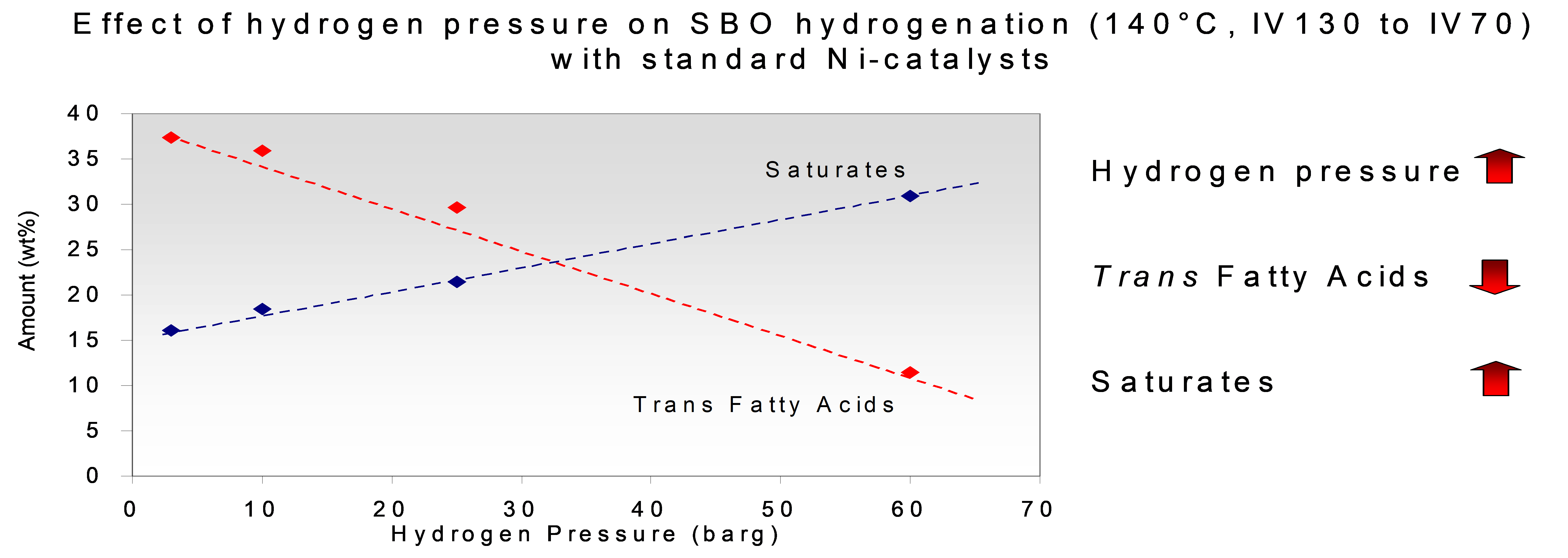
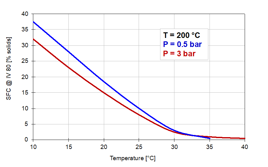
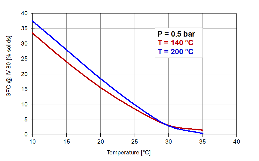
The effect of the reaction conditions on trans and saturate composition in the hydrogenation of soyabean oil is illustrated by the graphs shown in Figure 5 below:
Figure 5. The effect of pressure (left) and temperature (right) on the formation of trans-isomers and stearic acid.
If the pressure is taken to much higher values than industrial autoclaves in edible oil plants are capable of reaching, the effect is much more extreme, as illustrated in Figure 6 below:
Figure 6. Effect of pressure on the formation of trans-isomers and stearic acid.
The effect of the reaction conditions on the solids content at 80 IV in the hydrogenation of soyabean oil is illustrated by the graphs in Figure 7 below:
Figure 7. Solid fat contents of 80 IV samples produced under conditions of Figure 5.
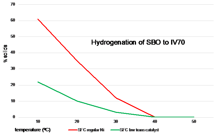
Often the question is asked whether it is possible to hydrogenate an oil partially and at the same time drastically reduce the formation of trans isomers. Even when certain modified nickel catalysts (which are not available on the market) or platinum catalysts (which are not economically viable and which have too low a linoleic acid selectivity) are used, the product loses all its firmness in the temperature range where manufacturers need the fat to be firm. This is illustrated in the figure below, in which soyabean oil was hydrogenated to IV70 with a regular nickel catalyst and with a modified catalyst with similar linoleic selectivity.
Figure 8. Solid Fat Contents of soyabean oil hardened to an IV of 70 with two different catalysts
5.2. Catalyst deactivation.
During use, the activity of the catalyst reduces due to different reasons.
Due to the free fatty acids present in the oil, some of the nickel dissolves in the form of nickel soaps. This is particularly true in the early stage of the hydrogenation, when the concentration of hydrogen in the oil is relatively low due to the high consumption of hydrogen at this stage, but also when relatively high temperatures are applied. Thanks to the presence of hydrogen, part of this nickel is reduced back to metallic nickel and the overall effect is that the small nickel crystallites (which contribute most to the metal surface area of the catalyst) tend to dissolve most quickly and that the metallic nickel tends to precipitate preferably on the larger crystallites. This causes the metal surface area to decrease during the course of the hydrogenation, which in turn causes the activity to be reduced.
Natural oils always contain impurities which can act as catalyst poisons. The most severe poison is sulphur, which is present in organic molecules in some types of oils. Apart from oils from animal sources (fish, tallow, lard) which today rarely serve as feedstocks for hydrogenation, there are also some vegetable oils which are notorious for their sulphur content. Examples are rapeseed/Canola and mustard seed oil. The effect of the sulphur is that the molecules in which the sulphur is contained (e.g. glucosinolates) are cracked in the hydrogenation environment, yielding products with exposed sulphur, which react with nickel, forming nickel sulphide. Where there is nickel sulphide, no hydrogen can be adsorbed on the nickel. Apart from reducing the activity, the presence of a partially sulphur-poisoned nickel surface (and consequently a low concentration of hydrogen atoms on the nickel) always leads to a higher concentration of trans-isomers. When trans-promoting partial hydrogenation is targeted, sulphur can be used as a promotor to form a high percentage (max. ca. 75 %) of the double bonds to be in the trans configuration. Thanks to the higher melting point of trans-isomers, this causes the solid fat content to be higher in the low-temperature range of the solid fat curves, resulting in a greater steepness of the solid fat profile. Accordingly, high trans fats are used as cocoa butter substitutes.
The effect of sulphur on the activity depends on several factors, one of them being the form in which sulphur occurs. Strongly bonded sulphur, such as in sulphates for instance, will not react with nickel. As a rule of thumb, one can use that each ppm of sulphur inactivates 0.001 – 0.002 % as nickel. As an example, a level of 10 mg/kg of sulphur (a common value in rapeseed/Canola oil) inactivates up to 0.02 % as nickel, or with a 20 % nickel catalyst, 1 kg of catalyst per tonne of oil. This corresponds with a common dosage level for effective hydrogenation of a sulphur-free oil.
Removal of sulphur in the feedstock prior to hydrogenation is generally most beneficial to the hydrogenation reaction. This is achieved to a great extent in the refining process. Some of the sulphur compounds are sensitive to high temperatures. Deodorisation at relatively high temperatures is therefore sometimes applied as a way to remove a great deal of the sulphur as sulphur-containing cracking products in the deodorisate.
In those cases where severe catalyst deactivation plays a role, an attempt can be made to reduce the consumption of catalyst by using the fact that nickel can react with much more sulphur than is needed to eliminate the catalytic activity. As an example, one could use a two-stage hydrogenation. In the first stage e,g, 10 – 20 % of the total amount of catalyst needed for the reaction would be added as a sacrificial dose to remove most of the sulphur. The rest of the catalyst is then added in the second stage to catalyse the hydrogenation reaction in a more or less poison-free oil. It is recommended, if possible, to add hydrogen in the first stage (even though no hydrogenation may take place) and to raise the temperature. This will create more favourable conditions for the sulphur containing molecules to be cracked and to expose their sulphur to the sacrificial catalyst in the first stage, rather than in the second stage.
Other common catalyst poisons are:
- Phosphorus compounds, in particular those that originate from phosphatides in seed oils. They are thought to deposit themselves on catalyst particles, covering the nickel on the outside and narrowing pore mouths. The latter has the same effect as using a narrow pore catalyst (see section 5.1.). This explains why high phosphorus levels tend to lead to a much-reduced selectivity. - Free fatty acids (see also section 4.). - Moisture. Water leads to hydrolysis and the formation of free fatty acids.
5.3. Catalyst reuse.
After fresh catalyst has been used for the first time, it still has some activity left, which raises the question whether or not it makes sense to reuse it. Some hydrogenation plant designs do not allow the catalyst to be reused in a safe way. In those designs that do allow the catalyst to be reused, about 50 % of the hardeners prefer not to reuse the catalyst. Some prefer to avoid the handling of used catalyst, while others prefer the consistency of using fresh catalyst over the uncertainty of how much activity is left and in the case of partial hardening, how much selectivity is still there. Those who do reuse the catalyst can adopt different reuse regimes:
- 2.1. The simplest way of reuse, applicable only in full hardening, is to start with a copious overdose of catalyst and redirect the used catalyst from the filter back into the new batch of oil. After a number of cycles, the catalyst has lost its activity to the extent that the batch times grow too long or the filtration properties of the catalyst deteriorate so filtration times get too long. Then the cycle can be started all over again with fresh catalyst.
- 2.2. The next simple way to reuse the catalyst entails making up for the activity lost during the first use by adding a small amount of fresh catalyst to the used catalyst. The disadvantage in partial hydrogenation is that in each following batch, the ratio of fresh vs. used catalyst becomes smaller and over time the selectivity of the blend is bound to change. This type of reuse is repeated until the filter is full or until filtration becomes too slow.
- 2.3. A reuse regime that was applied quite extensively in the past was the one whereby the lost activity was initially restored by adding fresh catalyst in each reuse cycle and subsequently, after a number of cycles, in each of the following batches, a fixed amount of filtered catalyst was discarded and replaced by fresh catalyst. In this way the total quantity of catalyst remained the same over many cycles and one could be assured of a relatively constant catalyst performance from batch to batch because the continuous turnover of catalyst ensured that the ratio of fresh and used catalyst remained the same. Modern filtration equipment however often does not allow this method to be applied.
- 2.4. Some companies have developed intricate systems of catalyst reuse. For instance, they may classify used catalyst in different groups, each of them having different properties, according to the feedstock and the number of times the catalyst has been used. They may set aside the different types of used catalyst and use them for different purposes, depending on the type of feedstock and the type of selectivity required, e.g. in terms of the steepness of the melting curve of the hardened oil. Even at times when much of the oil was hydrogenated partially and when in big parts of the world hardening plants were faced with a multitude of feedstocks (Europe, Korea, Japan), for most companies this system was too elaborate and too much prone to human error.
Quality control and R&D
The QC laboratory and the R&D laboratory of an edible oil hardening plant should be equipped with a number of analytical techniques. For detailed procedures I refer to the AOCS standard methods. The following are the most basic analytical requirements any lab should have and which in most cases are not specifically limited to use in hydrogenated fats:
- Melting point. The most convenient and probably most widely used method is the (Mettler) dropping point method.
- Solid fat profile. The most common and most convenient method is the determination of Solid Fat Content (SFC) by means of an NMR technique.
- Hardness test (penetrometer method).
- Iodine value.
- Chromatography (GLC).
- Trans-isomer content.
- Nickel content.
- Free fatty acid content (ffa) or acid value.
- Refractometry.
- Saponification value.
- Colour (mostly as Lovibond yellow, red and green).
- Peroxide value.
- Anisidine value.
- Stability tests.
In some QC laboratories a quick hydrogenation test is done as a QC test to assess the “hydrogenatability” of incoming oils.
An R&D laboratory should of course be equipped with one or more autoclaves. In R&D often a small size autoclave (usually 100 ml or larger) is used to do primary R&D work and a larger pilot plant reactor (typically 10 L. – a few hundred L.) is used to mimic more closely the commercial scale process and to produce larger quantities of products for further experimental processing or for evaluation purposes by customers.
Epilogue
Hydrogenation has been a well-established and useful tool to modify fats and oils for over 100 years. It has grown into a cost-effective way to produce hard stocks, to stabilise unsaturated oils and to modify the melting behaviour of fats. In particular, since the nineteen nineties of the last century, partial hydrogenation has come under scrutiny due to the trans-isomers produced during the process. They are believed to contribute to cardiovascular diseases. So far, no way has been found to completely eliminate the formation of trans-isomers during hydrogenation. Producers have therefore limited the use of partially hydrogenated fats in their final product blends and they are focusing more on (zero-trans) fully hydrogenated fats today, usually followed by blending and interesterification.
The cost-efficiency of hydrogenation depends to a great extent on the mixing efficiency of the reactor and the properties of the catalyst used.
Nickel has been the catalyst of choice since the early history of edible oil hydrogenation in the twentieth century. There are many types of nickel catalysts on the market that have specifically been developed for the hydrogenation of edible oils and fats.
Catalyst producers are generally knowledgeable in the field and they will advise their customers which catalyst works best for which application. The major producers are:
- BASF: https://catalysts.basf.com/products-and-industries/process-catalysts/chemical-catalysts/oleochemical-catalysts
- Evonik: https://catalysts.evonik.com/product/catalysts/en/about/
- Johnson Matthey: https://matthey.com/products-and-services/chemical-processes/chemical-catalysts/hydrogenation-catalysts
References
- Sabatier, P. and Senderens, J.B. Hydrogénations directes réalisées en présence du nickel réduit; préparation du hexahydrobenzène. Comptes Rendues, 120, 132 (1901).
- Normann, W., Process for converting unsaturated fatty acids or their glycerides into saturated compounds. British patent 1 515 assigned to Herforder Maschinenfett- und Ölfabrik Leprince und, Siveke (1903).
- Koritala, S. Moulton Sr, K.J., Friedrich, J.P., Frankel, E.N. and Kwolek, W.F. Continuous slurry hydrogenation of soybean oil with copper-chromite catalyst at high pressure. J. Am. Oil Chem. Soc.,61, 909-913 (1984).
- Hastert, R.C., Practical aspects of hydrogenation and soybean salad oil manufacture. J. Am. Oil Chem. Soc. 58, 169-174 (1981).
- Härröd, M., Hark, S van der, Holmqvist, A. and Moller, P. Selective hydrogenation of triglycerides at supercritical single-phase condition. Paper presented at the 3rd EuroFedLipid Congress, Edinburgh, page 85 in the Abstracts (2004)
- Pintauro, P. N. Electrocatalytic hydrogenation of edible oils. In Hydrogenation of Fats and Oils,Theory and Practice, 2nd Edition (List, G.R., King, J.W. (eds) AOCS Press) (2011).
- Koetsier, W. Hydrogenation of edible oils. Technology and applications. In Lipid Technologies and Applications (Gunstone, F.D., Padley,F.B. (eds) Marcel Dekker Inc.) (1997)
- Tiller, F.M., Li, W. Solid-liquid separation. In Encyclopedia of Chemical Processing (Li, S. (ed.) Taylor & Francis, Boca Raton, FL) (2006) DOI: 10.1081/E-ECHP-120007766.
- Dijkstra, A.J. Kinetics and mechanism of the hydrogenation process. The state of the art. Eur. J. Lipid Sci. Techn. 114, 985-998 (2012).
- Coenen, J.W.E. The rate of change in the perspective of time. Chemistry & Industry, 709-722 (1978).
- Dijkstra, A.J. (2012), Kinetics and mechanism of the hydrogenation process – the state of the art. Eur. J. Lipid Sci. Technol., 114: 985-998. https://doi.org/10.1002/ejlt.201100405
- Dijkstra, A.J. (2006), Revisiting the formation of trans isomers during partial hydrogenation of triacylglycerol oils. Eur. J. Lipid Sci. Technol., 108: 249-264. https://doi.org/10.1002/ejlt.200500335
In This Section
- Marine Oils
- Animal Fats
- Olive Oil
- Palm Oil
- Seed Preparation
- Expanding and Expelling
- Solvent Extraction
- Meal Desolventizing, Toasting, Drying and Cooling
- Introduction to Degumming
- Chemical Degumming
- Enzymatic Degumming
- Alkali Refining
- Optimization of Bleaching Process
- Silica Hydrogel and its Use in Edible Oil Processing
- Deodorization
- Hydrogenation Mechanism
- Chemical Interesterification
- Enzymatic Interesterification
- Solvent Fractionation
- Dry Fractionation
- Hydrogenation in Practice

![Hydrogenation plant [4] Hydrogenation plant [4]](/images/LipidLibrary/EdibleOil/Fig.3.png)
