Solvent Extraction
The Author: George E. Anderson, Crown Iron Works Company, P.O. Box 1364, Minneapolis, MN 55440 USA.
Background
One of the most basic needs of mankind is an abundant and reliable food supply. In the modern world, one major source of protein and vegetable oil is from oilseeds, particularly the soybean – an abundant resource which is largely processed using solvent extraction, an efficient and reliable means to separate the high-protein meal solids from the high-energy edible oil. The second most prevalent solvent-extracted oilseed is rapeseed and/or the varieties called Canola [1]. Sunflower is also quite high in volume.
A much lower volume or secondary use for soybean oil and rapeseed oil, gaining popularity in recent years, is as a feedstock for biodiesel fuels for diesel engines. There are many other products such as oleochemicals made from oilseeds – and often these are provided with a solvent extraction system as a part of the total supply process.
I mentioned “Efficient and reliable”. All through history, not just in the present century, there has been a premium on providing food with the least work or energy required. Indeed, in the distant past when the work was done by hand – often your own hand - it was nearly automatic that everyone would be sincere about energy efficiency! The same is perhaps true on the smaller or better-managed farms of today. For most of us in the modern food processing industry, however, the commitment is far less directly related to our personal labor and has become more intellectual and economic, motivated by survival in economic competition. Our processes continue to improve, the tools for improving efficiency are themselves better than ever, and with greater detail and elegance we realize our world is a far better place if we make efficient use of our resources and limit the damage we do to the environment and other forms of life. We might call it “good stewardship”. Because the commitment today less often results in actual physical labor for the decision maker, it is essential that each of us at all levels of government, family, or industry (and even in retirement) remember to make real and nearby energy improvements in all our personal actions as well as professional decisions.
Why solvent extraction? One early means of separation was physical pressure to ‘squeeze the oil out’. The most energy efficient, practical embodiment of that method is the modern screw press. This is a conveyor screw with a slotted cage surrounding it and a screw with diminishing space for the solid material as the material proceeds from pitch to pitch of the screw. Eventually, as the free space is progressively restricted, the oil is squeezed out of the solids and through the slots. More than half of the oil is easily removed in this way, but perhaps 7% or 8% residual oil is left in the solids, the process uses considerable horsepower, there is considerable wear and maintenance, and it takes many machines for high capacity. In comparison, solvent extraction with hexane (the primary solvent used worldwide) will remove all but about ½% of residual oil, uses less horse power, and requires less maintenance. It is relatively efficient and reliable, and this is one reason why solvent extraction is the primary means of separating large tonnages of oil from protein meal.
Why hexane? Actually, it is not a pure n-hexane but a mix of isomers with very similar properties sometimes called extraction hexane or commercial hexane. The properties shown in Table 1 are listed in the NFPA-36 safety standard for solvent extraction [2]. It does appear to have slightly greater ability to extract oil from oilseeds than does pure n-hexane, perhaps due to the variety of isomers present. Hexane has about the best characteristics of the many solvents tried over the years. With a boiling point of 156°F (69°C) it is a liquid in all but the most extreme climates of the world. With a fairly high volatility and a low sensible heat of 144 Btu/lb (335 kJ/kg) it is relatively easy to remove from the solids and oil with low energy use. It has an azeotrope, a slightly reduced 143°F (61.6°C) boiling temperature when in the presence of water or steam and resulting in a vapor coming off at about 95% by weight hexane and 5% by weight water. The azeotrope is convenient for efficient removal of the solvent from solids (or “meal”) using direct steam contact. Hexane has a long record of use without as much irritation of human skin or the immediate or severe toxicity of many competitive solvents. It does not mix with water, allowing fairly simple processes to keep it in the system while water passes through the extraction process as moisture in the seed, meal, oil or air. Hexane has a good and aggressive capability to dissolve and mix with vegetable oils so that it can wash the desired oils out of a fibrous or solid material. It is selective and leaves the proteins, sugars and some undesired gums largely undisturbed in the meal. Last but not least, hexane has a relatively ‘tolerable’ odor and a low tendency to cause discomfort when one is subjected to a brief exposure.
| Table 1. Physical properties of typical commercial hexane and isohexane | ||
| Property | Hexane | Isohexane mixed isomers |
|---|---|---|
| Flammable limits (percent by vol.) | 1.2-7.7 | 1.0-7.0 |
| Ignition temperature (°C) | 225 | 264 |
| Flash point (°C), closed cup | -26 | -18 |
| Molecular weight | 86.2 | 86.2 |
| Melting point (°C) | -94 | -154 |
| Boiling range at 1 atm (1.0 bar) (°C) | 67-69 | 56-60 |
| Specific gravity at 60°F (15.6°C) | 0.68 | 0.66 |
| Pounds per gal at 60°F (15.6°C) | 5.63 | 5.52 |
| Vapor density (air = 1) | ~3 | ~3 |
| Latent heat of vaporization at 1 atm (1.0 bar), (kcal/kg) | 79.6 | N.A. |
| Vapor pressure at 37.8°C (kPa) | 38.1 | 39.4 |
| Specific heat liquid (kcal per kg-°C at 15.6°C) | 0.531 | N.A. |
| Specific heat vapor (kcal per kg-°C at 15.6°C) | 0.339 | N.A. |
| Solubility in water [moles per L at 60°F (15.6°C)] | negligible | negligible |
| N.A. - data not available. Adapted from NFPA-36, 2009. | ||
Other solvents? Hexane has maintained the dominant position as a solvent for the major plants which extract oil from oilseeds. Every so often the media discusses a new solvent or means of extraction which may replace solvent extraction with hexane, but (so far) the existing technology has sufficient virtues to maintain credibility while it continues to be developed in a competitive market. Widespread use and familiarity ensures that many people and resources will continue to improve on stubborn problems and optimize the hexane process. There is also the advantage of well-understood industry expectations for performance, the availability of trained personnel, and established standards for safe use. Any proposed replacement must exceed hexane’s basic advantages and still might be expected to require a lot of time, development and capital investment to work as well.
It should be noted that other solvents may be required to produce different and specific products. For example, an alcohol-water mixture is used in an additional extraction step (after hexane extraction) to produce soy protein concentrate (or “SPC”) by removing the sugars from standard soybean meal. Various alcohols, isohexane, heptane, butane – many other solvents have found applications in niche markets. For the standard oil removal plant, only isohexane – an isomer with properties very close to hexane - has replaced hexane in a significant number of extraction plants. Hexane is the focus of this article since it is still the highest volume and most commonly used.
Flammability. Hexane does have one weakness which is universally mentioned: when hexane vapor is mixed with air in roughly a range from 1.2% to 7.7% by volume, the mixture is flammable. Over the last century, many processing plants have had fires or even explosions which caused serious damage. The NFPA-36 standard is one result: a set of rules for construction of these plants which, if followed and well managed, should provide a very safe working environment and a reliable means of production. It should be noted that gasoline is also inherently and potentially dangerous, yet millions of grandmothers top off their gas tanks weekly. Apparently they have mastered a few simple and reliable rules about not smoking, avoiding static electricity, avoiding significant personal contact with liquid or vapors, and maintaining a vigilant attitude during fueling, etc. I do not say this to minimize the danger – but it should be evident that fire hazards can be dealt with effectively, there are other hazards to any process in addition to fire, and thus far the flammability of hexane has not kept it from out-competing other solvents or means of extraction. One result of this flammability, however, is the necessity to avoid significant amounts of hexane from escaping from the plant process in the process air, water, meal or oil, or simply in losses due to poor equipment maintenance, frequent shutdowns, or poor housekeeping.
The typical percolation extractor is designed to operate at a very slight vacuum of perhaps -0.4” water (-10 mm water) in an effort to enhance safety. As noted, a mixture with about 5% hexane in 95% air is in the flammable range, but 5% air uniformly mixed with 95% hexane is not flammable. Therefore, a slight leak of air into the pure hexane inside the machine may not usually or quickly result in a fire or significant explosion hazard, but a slight leak of hexane out of the machine and into the pure air of the extraction room may more often be possible to ignite and perhaps cause a more energetic explosion. It is also often true that the interior of a vessel or machine may not have a source of ignition – no spark, gasoline engine, open flame, etc. – whereas the outside environment may be less predictable. (Caution: read up on safety and discuss the issue with experienced people before presuming that the shallow understanding of any one simple rule is a guarantee of safety!)
Hexane is also costly, and it is considered a pollutant if it escapes from the process. These are additional reasons to avoid the escape of hexane from the process.
The Process Schematic
Plant Location. Most extraction systems are located near the farm fields which supply the oilseeds, or on ports or rail lines suitable to moving the very large volumes of oilseed and products. The plants are often large enough to process perhaps 1000 to 6000 tons of seed per day, and it may be beneficial to be near a city large enough to provide mechanical services, operating staff, reliable electric power, housing for visiting technicians, etc. There are perhaps 55 commercial-scale plants in the USA.
Figure 1 shows a schematic of how a typical plant for soybeans may be organized. Seed is received usually from large trucks (or rail cars, or barges), cleaned, weighed, dried if necessary for safe storage, and put in bins. It is then drawn from storage as needed to provide feed for the extraction process. It may be put in a ‘day bin’ to allow processing from the various silos in the best sequence according to age, moisture, or quality of seed. While the process is in operation, seed may be dried or otherwise sorted in bins to improve the smooth operation of the plant. Flow from the day bin would be continuous, (one would hope) allowing the entire process system to run very smoothly and evenly for maximum efficiency.
Figure 1. Processing of soybeans.
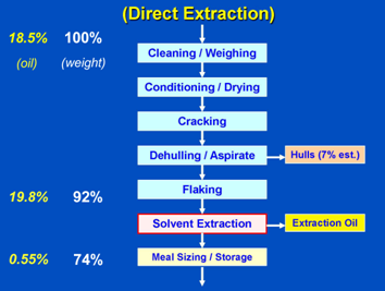
Figure 2 is the process for rapeseed or other high-oil seeds. The seeds differ in that soybeans have about 20% by weight of oil, and rapeseed has about 40% oil. The higher oil products often require an added step called pre-pressing. Put simply, the high oil content makes it difficult to adequately flake the oilseed and cook it for solvent extraction without oil coming free of the seed and fouling equipment. Furthermore, the 40% oil content would require much more than the optimum energy for removal of solvent from miscella in extraction. Therefore, the screw press technology is used before extraction to better prepare the high oil seeds for the extraction process. It is partly practical experience and partly better balancing or optimization of the plant for low energy – but most high oil percentage seeds have pre-press systems before extraction. Such seeds are commonly rapeseed, canola, sunflower, safflower, and the like.
Figure 2. Processing of canola/rapeseed.
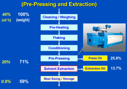
In general, a pre-press system followed by solvent extraction may be an option when the oilseed contains more than about 23% oil. This combination combines the best of each system: the pressing operation removes the higher percentages of oil which are by far the easiest to squeeze out of the solids, and the solvent extraction process is best at removing oil from about 20% down to near ½%. In Figure 2, it is worth noting that a plant to process rapeseed with pre-pressing followed by extraction will often reduce the oil content from about 40% to 20% in the presses and from 20% to 0.8% in extraction, and that (after adjustments for moisture changes during the process) the press oil produced may be roughly 25.8% of the raw seed, while the extraction oil may be about 13.7% of the raw seed. Most of the oil will be press oil.
The Extraction Area and Controlled Area
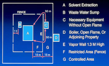
As was noted, hexane is flammable and it is therefore essential to do two things: first is to protect adjacent properties, public roadways, and untrained people who may experience gasoline filling stations but are otherwise not used to the hazards of flammable liquids being present in their environment. Second is to protect the process system and operators from the hazards of people who are not specifically trained in the safe handling of flammable hexane – with their smoking, hot automobile engines, sparking lawn mowers, cell-phones, kids with matches, and scratchy boot nails. Therefore, the extraction process where hexane is present is confined to a building about 100 feet from “the rest of the world”. This process is specially constructed to safely contain the solvent in the vessels and to eliminate sources of ignition. Only trained personnel are admitted in to this area. Usually, the process area is located in the center of a restricted area (inside a fence) and a larger controlled area (perhaps in a fence, but in some way defined and having limited access.)
Long conveyors move the material in to the solvent extraction area, and another conveyor moves the meal back out while the oil is pumped out to storage tanks. All conveyors and piping systems are designed to minimize the chance of solvent liquid or vapor being transferred out of the extraction area. Figure 3 is a simplified layout of an extraction plant
Figure 3. Solvent extraction - distance diagram. Reference NFPA-36, (2009 simplified).
The Solvent Extractor
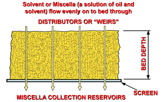
Percolation Extractor: At the center of the extraction plant is the extractor. A percolation-type extractor is by far the most commonly used for the removal of oil from oilseeds such as soybeans, canola, or sunflower. Figure 4 shows that in ‘percolation’ a liquid drains down through a porous bed of material and through a screen which supports the material - similar to a coffee percolator. As the solvent (usually hexane) passes down through the bed of oil-bearing material, the oil is dissolved in the solvent and carried away. When properly carried out with stages of extraction (as will be described), the extraction process results in a very good separation of the edible oil from the solids or nutritious meal fraction.
Figure 4. Diagram of percolation extractor.
Three Common Types of Extractor: Figure 5 shows several common types of extractor. These machines might be categorized in the following manner (with approximate bed depths): The Crown or ‘vertical loop’ extractor typically has a relatively shallow bed (0.3-1 m) and a bed useful length about 50 times as long as it is deep, but curved into a loop for compactness. The straight-line linear units often have a medium depth (0.9-1.8 m) and length about 15 times as long. The round extractors commonly have a deeper bed (1.6-2.9 m) held in wedge-shaped cells defined by distinct, solid cell walls; often there are about 16 to 24 cells. (One perhaps unusual machine operating on expanded soybean collets had well over 3.7 m bed depth.) The proportions of this geometry require that the bed be contained in cells or baskets such that material will not be washed out of position, and the cell walls force the miscella to travel within the column and into the correct tank below.
Figure 5. Designs of three extractors
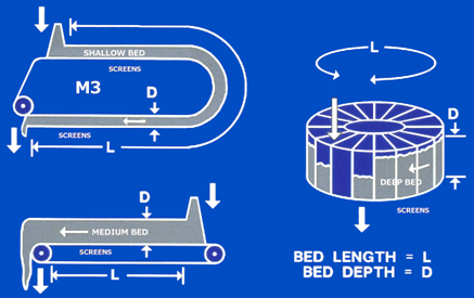
Common to all these machines is the need for a large volume of material in full contact with the solvent. Actually, there is only a moment of contact with the pure solvent, near the point where the solvent enters the machine, because the solvent immediately begins to pick up some oil and then becomes a mixture called ‘miscella’. One can see in Figure 5 the volume of the bed in each machine is the bed length times the bed depth times the bed width. No extraction will occur before the first wash initiates contact of solvent and solids, and no oil or solvent can be removed after the final drainage area where the screen ends. Therefore, we will only consider that part of the flake bed as the useful volume or wet volume. All of the extraction work must be accomplished in this volume of flakes, and this also defines the effective retention time of the machine.
These machines are large. For example, one brand of extractor capable of 9000 metric tons per day soy input capacity has a bed depth of 1.0 m, width of 4.3 m, and machine overall length of more than 46 m. The other manufacturers will achieve a similar or even larger useful volume using dimensions appropriate to their particular shape of machine. Each type of machine has gone through many years of improvement and optimization of features, with the result that equipment of each design from major manufacturers is generally reliable and efficient.
Most of these extractors will operate on most common oilseeds with little physical changes to the extractor or surrounding equipment. Of course, the preparation of the seed may be different as mentioned above and in other articles in the Lipid Library. As to the extraction machines, the most frequent difference is additional stainless steel components for oilseeds or solvents which are more corrosive. Many of the factors important for the efficient extraction of soybeans are very similar for other oilseeds, though certain extraction settings and the relative size of the various pieces of equipment may need to be altered.
Shallow and Deep Bed Machines: The appropriate dimensions for different shapes of extractor lead some to have a deeper depth of bed to attain the required volume. Some tend to call an extractor with a bed up to about 1 meter as a “shallow bed machine” and one with much more than 1 meter as “deep bed”. Both shallow and deep bed machines can extract very well. It is clear, however, that there are differences in preparation of the seed and other operating settings to provide the greatest efficiency with different design machines. For example, in a significantly deeper bed there is more weight of material (and sometimes liquid) on the material down near the screen. Therefore, preparation for a deep bed machine may have expanders added to form rugged collets; this has the advantage of also increasing density and reducing the solvent retained after extraction. Shallow bed machines can use thinner flakes or more fragile and dusty materials; this has the advantage of eliminating expanders or other preparation equipment.
Importance of Adequate Washing: Some sources have suggested that extraction only occurs directly under a solvent or miscella wash, where the bed is fully saturated with miscella. Tests performed in commercial machines in the late 1960s compared extraction with numerous small washes per stage to extraction with the same total wash volume but concentrated in fewer large washes per stage. The tests indicated that extraction will proceed normally provided that there is sufficient fresh solvent to the extractor, good countercurrent stages, and the correct total volume of wash per stage to remove and replace miscella as it becomes laden with oil [3]. We also have the support of logic: a flooded bed has about 55% liquid by weight, and a partly drained bed (about 1 minute without wash) between stages has perhaps 40% solvent by weight (the fully drained bed, as a limit, may have about 30% after final drainage). At either 55% or 40% the amount of miscella is far more than the amount of oil in the bed – often only 1% to 5% - and the 40% undrained miscella is concentrated inside the particle where it is still quite aggressive in contacting and dissolving oil. It is important to have effective countercurrent stages, to have pure final solvent, to wash all particles uniformly, and to wash sufficiently to change out the higher concentration miscella in each stage.
Dry Loading versus Slurry Loading: To get good contact in some designs of deep bed extractor with `cells' or `baskets', it may be helpful to totally flood the irregular material surface with solvent so as to wet every area of the bed. There is also a potential for `channeling' in which solvent runs down the side walls or cell walls and does not contact some bed areas sufficiently. Deep bed units counteract this quite often by filling in a slurry, to provide a good initial soak. Once the material is soaked it will tend to `wick in' later solvent washes, reducing or preventing these ‘channeling’ effects. A shallow bed unit is usually loaded dry. But it is essential that the solvent be distributed evenly across the full width of the shallow bed as it travels by to get good contact with all the particles. Both the shallow and deep bed designs extract efficiently when run correctly.
Screens: Many extractors have screens which move with the bed. In some machines they are part of a hinged bottom of the cell in which each column of meal is carried. In others the screens are part of a moving belt under the bed. In many newer extractors, the screen is stationary and is made up of vee-shaped bars which run lengthwise, parallel to the motion of the chain and bed. The stationary screen is clipped securely into the casing or housing of the machine. The result is that the material slides over the smooth steel bars and smooth drainage slots and brushes obstructions along the slots until they fall through. The slots are relieved on the bottom side to allow more free passage of any particles which may be small enough to pass through the gap. (These particles are then pumped back on top of the bed by the recycle pumps.)
Automatic Level and Speed Control: One useful feature used on extractors from some manufacturers is an automatic level control system on the inlet hopper. The system adjusts the speed of the drive to exactly match the feed rate of material to the machine.
In several designs, the concept and hardware are fairly simple: There is a blade above the chain at the inlet area that always ‘cuts off’ the bed at the full operating depth. This means that the chain speed is directly proportional to the tons of feed material per day that the machine is processing. A sensor measures the depth of the material in the extractor feed hopper, and if the level is too high it gradually speeds up the extractor chain to pull more material into the extractor. If the level is too low it gradually slows down the extractor to allow material to build up in the inlet hopper.
The first benefit is that this is done automatically, without continual operator attention. A second benefit is that, because it is a continuous and automatic adjustment, it does not need to run with the bed only about 85% full to allow the operator a reasonable margin for error. Therefore, the extractor always maintains a full bed and always uses its maximum volume and retention to efficiently process the tonnage supplied.
Uniform Discharge Rate to Desolventizer-Toaster (DT): The discharge of solid material from a shallow bed extractor may be relatively uniform. In many extractors the bed is in about 20 distinct cells, and discharge consists of dropping a larger amount of meal at a time onto the discharge conveyor. In either case, it is an advantage if the flow be uniform in both flowrate and solvent content by the time it enters the DT. If the type of extractor does not discharge evenly, the conveyors may incorporate a retention bin with an agitator to smooth out the flow. If the flow is relatively uniform the desolventizer can run more steadily, with less damping of its controls and less surging which may harm its ability to desolventize and cook uniformly or use steam efficiently.
Hydroclone: Many plants worldwide for over 50 years have used hydroclones (also called hydrocyclones or liquid cyclones) to clarify miscella before it goes to the distillation system. Extractor miscella, containing a very small content of fine dust, enters the hydroclone at high velocity and spins rapidly. The heavier dust is thrown to the cyclone wall. This dust and a small amount of miscella fall down the cyclone walls, pass through the bottom discharge orifice, return to the extractor, and are distributed back on the flake bed surface. The bed filters out the fines and they go with the solids to the DT. Most of the miscella goes up the center of the cyclone and to the evaporator - with most traces of fines removed.
In most cases, soybean miscella from a properly operated hydroclone is clear enough to keep distillation equipment clean enough for plant operations and for lower-quality lecithin production - but not for higher-quality lecithin.
Basic Extraction Theory
Extraction theory can be put very simply: we are trying to soak oil out of small particles or flakes of material with a solvent, usually hexane. The solvent has to travel into the particles, soften up and dissolve the oil, and the miscella (the solution of oil in the solvent) then must travel out of the particles and be washed away by still more solvent.
Five Basic Requirements: To achieve effective removal of oil from most oilseeds using solvent extraction, we may speak of these basic requirements. All kinds of extractor require proper preparation of the oilseed to achieve good results and one often hears the phrase, “It all begins in preparation.” The first requirement is related to the preparation area and steps including conditioning, cracking, dehulling, flaking, perhaps pre-pressing and expanding:
- PREPARATION: The term “conditioning” means to heat the seed and hold it for proper time and temperature to soften and rupture oil-bearing cells, make the seed more pliable to reduce generation of fine dust in flaking, and keep the extractor warm. Correctly prepared materials have high porosity, a large surface area and thin flakes (or cell breakage in well designed presses) to allow rapid penetration by solvent, and ruptured oil cells so that solvent can reach the oil. The material must also allow good percolation – the rapid flow of solvent down through the bed and screen so that the oil can be transported out of the bed.
Once the seed is prepared into appropriate flakes, collets or cake, it is conveyed to extraction. Then we have four more requirements:
-
SOLVENT: A high enough solvent ratio (the ratio of solvent to solids entering the extractor) and a sufficient number of effective stages of wash. These stages are to be “countercurrent” with declining oil concentration until the final pure solvent wash. A machine with more and better stages can operate with less solvent input (a lower solvent ratio and less solvent in the miscella) and lower costs in distillation. Efficient stages keep the miscella in later stages at the lowest possible oil content so that miscella trapped in particles going to the DT will not contain much oil.
- CONTACT: This requires correctly prepared material and an extractor designed to be “forgiving” – a design leading to the most effective washing and drainage with a wide variety of materials, even low-quality or damaged seed. A shallow flake bed helps reduce time at each stage and in final drainage. It also reduces the weight of the bed above which may otherwise crush fragile flakes. Specially designed stationary screens provide reliable flow of miscella and removal of solvent and oil.
- TIME: There must be enough time for the dissolving and flow processes to occur. Time is best utilized if an automatic control keeps the bed at full depth for maximum extractor volume and time, if the extractor drains rapidly at each stage and particularly at the final drainage so that time is not wasted, if the extractor is large enough, and if the material is made more dense – sometimes by use of an expander.
- TEMPERATURE: There must be a sufficiently high temperature at the extractor inlet to allow the entire extractor to operate at or near the boiling point of the solvent. Extraction consists of dissolving, mixing and flow processes; just like washing grease off a plate in the sink, it works better and faster when hot.
Temperature is a little more complex topic than most people realize. Because the extractor is usually designed to operate near ambient pressure (with very slight vacuum), the boiling point of hexane inside is about 156°F (69°C). However, because there is hexane and water held in intimate contact throughout the extractor bed, any vapor which comes off the bed will be near the azeotrope temperature of about 143°F (61.7°C) and that will be the approximate maximum for operation of the extractor. Even pure hexane heated to 156°F (69°C) before entry to the extractor will boil some as it contacts the water in the flake bed. Any such boiling in the bed will reduce drainage of solvent and hinder extraction. Therefore, the practical result is that the extraction bed will have a maximum efficient temperature of about 140-150°F (60-66°C) and it will resist going to higher temperatures by boiling off a lot of vapor. If material is introduced to the extractor too hot it will cause a great deal of boiling off of solvent and water – and reduce extraction drainage and reduce extraction efficiency.
Operate Near the Azeotrope! It is difficult to operate above the azeotrope. But it is very desirable to operate close to 142-145°F (61-63°C) at all points in the extractor. Operating at the hottest reasonable temperature makes the solvent and oil as low viscosity as possible and promotes rapid dissolving, mixing and flow. This allows the fastest possible extraction and better extraction results. Furthermore, since the extractor is only designed to operate near ambient pressure, any temperature below the azeotrope will result in a lot of air in the extractor. If temperature is very low the elevated air (and oxygen) content could even become a hazard for fire, but usually it is more of a concern due to internal corrosion of the extractor. Experience shows that where an extractor is cold inside, it has high air contact, and high oxidation of steel – and may eventually cut away enough metal to leak or have some structural problem.
Shallow bed and deep bed machines use different strategies and features to attain high efficiency. The following will provide more detail on various methods and features which may lead to efficient extraction.
Material Extraction Curve: Many investigators have presented their conclusions regarding the extraction rate of soybeans at various thicknesses of flake. Usually the data is presented as a single curve on a graph indicating the oil remaining in the solids at each point in time as the particles pass through the extractor. For the moment, I will call this the material extraction curve. Good discussions of the shape of this curve and presentations of both theoretical and test data are presented in an excellent early paper by Depmer [4], several versions by various authors are discussed in Bailey’s Industrial Oil and Fat Products [5], and an attempt at a rigorous theoretical approach is presented in two papers by Karnofsky [6,7]. It is not my purpose to discuss these at any length, but I should comment that there are significant differences in the conclusions of the various authors, and some of the results do not seem very close to practical results observed in real extraction systems. Each, however, documents the fact that thinner flakes typically extract much faster. When the soybean is cracked into somewhat large fragments or cracks and the final flake is relatively thin, that means that there has been considerable plastic flow of the material and more damage to the internal cell structure of the material. This creates fissures which allow more avenues for the free flow of solvent to contact the oil and increases the flow of all liquids in to or out of the particle. A thin flake also has more oil directly at the larger surface area and available for easy and rapid initial extraction. A thin flake also has a shorter distance for hexane to penetrate to reach and remove the last traces of oil. On Figure 6 I have provided two curves, and the lower red curve is the approximate material extraction curve as calculated by proprietary software we developed, based in theory but ‘informed’ by many data points in a long-term proprietary database. [8] Figure 6, however, also has an upper curve I have not seen except in our software; the lower curve is only “most” of the story about residual oil.
Figure 6. Material extraction curves for solvent extraction. Copyright: Crown Iron Works Company, 2011.
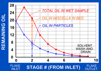
Countercurrent Flow: A primary objective of extraction is to remove as much oil as possible before the solids and any remaining liquids proceed to the desolventizer. One might think it is as simple as getting the undissolved oil left in the solids as low as possible, in accordance with the material extraction curve. However, there is also significant oil left in the miscella which is not completely washed off in the final solvent rinse. This can be understood better by looking at the extraction curves of Figure 6. It shows a lower curve, which shows the undissolved oil left in solids, and an upper curve which adds the oil in the miscella at each “stage” of extraction. To be clear, the difference between these curves is the amount of oil in the miscella, and the top curve is the total oil in what would remain if one were to take a sample of the miscella soaked bed at that point in the extractor and boil off the solvent so that all the oil in solids and the oil in miscella were left in the bed.
One can see that the flakes very near the inlet will still be close to their original oil content – 20% if they are soybean flakes. When this material is soaked in a nearly equal weight of miscella containing about 28% oil, the total oil in that same volume of extractor bed increases considerably; if one then were to quickly boil off the solvent before any drainage occurred, the result would be about 35% by weight oil in the flakes. (If one were able to wash off all the miscella with a quick and idealized rinse of solvent, the result would be close to the 20% - although in practice this will vary a lot because initial extraction is very rapid and all the miscella cannot be washed off from the surface and interior passages of the material.)
This “thought experiment” makes it obvious that one cannot allow high oil content miscella to be used near the discharge end of the extractor process because the solvent wash cannot remove all of it – and excess oil will go to the DT. Furthermore, the pure final washes of hexane should be very pure hexane or excess oil will be left in the material after much – but not all – of the solvent drains off in the last part of the extractor.
To avoid this problem, one could imagine a very simple extractor using a large amount of fresh solvent in every stage. However, it would be too costly to operate because this huge amount of solvent would all have to be distilled to recover the oil.
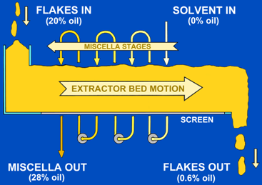
Therefore, fresh solvent use is kept to a minimum by the use of countercurrent stages of miscella. Figure 7 shows a simple diagram of this, a simple straight line extractor in which the solids are going from left to right in a machine, and the solvent is entering at the right end of the machine. The fresh solvent is first passing through the solids which have already been fairly well extracted. The solvent is then reused in multiple stages towards the left end, passing through the bed repeatedly, picking up oil and becoming a more concentrated miscella. This oil-rich miscella still has sufficient solvent content to extract effectively further to the left, where the solids contain more oil. Finally, the miscella exits at the left end of the machine. The flow of the solids from left to right is opposite of the flow of the solvent from right to left - and so we call this countercurrent or counter-flow. Virtually all commercial extractors make some attempt to use this basic flow method.
Figure 7. Diagram of countercurrent flow. Copyright: Crown Iron Works Company, 2011.
A Focus on Soybeans, the Most Common Oilseed
Soybeans are a special case in part because they are the highest tonnage of all the solvent extracted oilseeds world wide – about 56% of oilseeds processed by solvent extraction [1]. Because it is the most common oilseed processed and to maintain a clear step-by-step presentation, I will focus on the preparation and extraction of soybeans and point some of the differences when processing other seeds.
Soybeans are about 7% hull by weight. The hull is a paper-thin shell surrounding each seed that is high in fiber and low in oil; it is very low density unless ground quite fine, and therefore takes up a lot of space in costly process equipment. Being very low in oil, it is not particularly profitable to extract. It is also very low in protein and, when it is removed early in the process, the extracted meal has a significantly higher protein percentage and market value. For all these reasons, one of the first steps in the total process for soybeans is often a dehulling of the seed. In summary, removal of perhaps 90% of that 7% of hull reduces the volume going through extraction, reduces the energy for desolventizing, increases the meal protein percentage, and gives a by-product that has at least some value – the hulls. Most soybean systems in the USA and Europe, and increasingly in South America and the rest of the world, have dehulling systems. This dehulling function is usually integrated with other preparation systems to crack, heat and flake the material to make it ready for the solvent extractor. The dehulling process and the other steps in preparation are described elsewhere on this site.
Soybean Preparation: This should provide material with the following characteristics:
-
Cracked into 4 to 8 pieces per soybean using sharp serrated rolls. Cracks should be large enough to provide good distortion during flaking, but not so large as to require excessive flaker power or reduced capacity.
- Dehulled: This is done mostly to improve the protein level of the meal. However, it also reduces the tonnage going to extraction and increases the density in the extractor - leading to more retention time.
- Conditioned: Material to the flakers should generally be about 158°F (70°C) and final flakes at the extractor should be about 147-154°F (64-68°C) and from 9% to 10% moisture.
- Flaked to cause breakage of cell structure to release the oil for ease of extraction. For shallow bed extractors, perhaps flakes of 0.012" to 0.015" (0.30 mm - 0.38 mm). For deeper beds, perhaps flakes of 0.013" to 0.017" (0.33 mm - 0.43 mm).
- Avoid unflaked particles! Less than 0.3% is reasonable to avoid high average residual oil and very uneven test results.
- Low fines content so that it will not block drainage of miscella or leave excessive fines in the miscella.
- Good draining material, appropriate to the extractor. Expanders may be used to form tough, porous collets (provide a cooler to reduce the temperature of the collets).
With properly prepared soybean material and sufficient extraction time, it is often possible to achieve about 0.35 to 0.60% residual oil in spent flakes.
Optional Use of Expanders: Many plants worldwide use expanders after the flakers to further prepare soybeans for extraction.
The advantages include:
- The same extraction with slightly thicker flakes.
- Higher density in the extractor.
- Better drainage (very important on deep bed units).
- Lower solvent content to the DT (very important on deep bed units).
- Increased lecithin yield.
- Possible reductions in phosphorus content of crude oil.
Disadvantages include:
- The cost, space and maintenance of added cookers, expanders, and the collet cooler.
- Increased steam and electric power use in preparation.
- Electric power and maintenance of the expander and accessories.
- Reported problems with cloudy miscella, foam, and fines deposits in distillation.
- Increases in neutral oil loss in the alkaline refining process (“higher NOL”), with a significant economic cost.
- Uncertain advantages: will the advantages be sufficient to offset the disadvantages with a given combination of equipment and market economics?
Many processors add a collet cooler after the expander to reduce the collet temperature to the normal 150ºF (65ºC) at the extractor, so as to avoid boiling of solvent in the extractor. Properly used expanders provide similar benefits in either a deep bed or shallow bed extractor. However, they will usually be of most benefit when using a deep bed extractor, to an inefficient plant due to a smaller than desired extractor or DT, or a plant with an extractor having specific drainage problems.
Take Care Not to Generate Fines: At all points in the process, from the flakers or presses through the conveying, extraction, spent flake conveying and to the entry of the DT – it is important to avoid generation of excess fines. Specifically, avoid unnecessary transitions between conveyors, avoid unneeded drops from a high elevation, avoid unneeded agitators in bins, and certainly avoid plug screws which have excessive rpm compared to that required for the tonnage.
Guidelines: “Residual Oil in Solvent Extraction”
To summarize, extraction depends on five basic factors:
-
PREPARATION: As we have just discussed.
- SOLVENT: Pure, good-quality solvent, with enough flowrate for the tonnage processed, and with a sufficient number of effective countercurrent stages.
- CONTACT: Correctly prepared material with high surface area and good porosity, and a machine providing good contact for effective washing and drainage.
- TIME: Perhaps 30 to 50 minutes for soybeans depending on bed depth, flake thickness and other variables, to allow the dissolving and flow processes to occur.
- TEMPERATURE: Hot enough to maintain rapid extraction in the time available.
Figure 8 is a copy of a single sheet guideline entitled “RESIDUAL OIL ESTIMATE – SOY” [9]. It predicts the effects of major variables such as flake thickness and extractor temperature on the residual oil of extracted meal. The chart deals with soybeans - but most of the factors are similar for other products
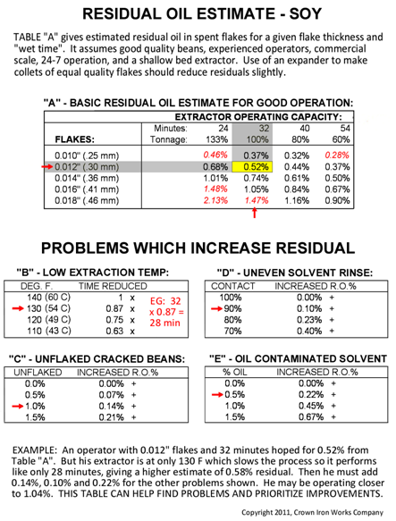
The chart should be self explanatory, but here is a quick summary of how to use it: Enter part “A” with the correct, measured flake thickness and the wet time of the extractor (from first wash to the end of the final drain screen). If the extractor is operating with the average temperature of the bed lower than 140°F (60°C) then look at part “B” and reduce the time by the appropriate factor, enter part “A” again, and find a slightly increased residual oil prediction. If there are other problems such as unflaked cracked soybeans in the feed to the extractor (“C”) or poorly distributed solvent final wash such that not all particles are contacted (“D”) or oil contamination of the solvent (“E”), then add the appropriate values for increased residual oil. In the example, a plant which should operate at 0.52% is more likely to operate at 1.04% residual oil due to problems in all these areas. Management can use this guideline to identify problems, estimate the importance of each, and prioritize improvements they may wish to make to their plant or operating methods.
Keep in mind that this chart is intended to be used with correctly conditioned seed of good quality, and is only applicable with a shallow bed extractor. Deeper bed machines will usually require more time for several good reasons; a major one is the added time for final drainage through a deeper bed to reach a reasonably uniform and low hexane content, appropriate for entry to the DT.
A Word about Safety and Training
 I have not concentrated on safety in this paper. However, safety is an important aspect in extraction plants due to the use of several chemicals, the flammability of hexane, the physical requirements of grain storage and handling, and the operation and maintenance of machinery of all sizes and descriptions. Most accidental injuries appear to be from mechanical causes such as falls and failure to lock-out machines being maintained. Fire or explosion, however, can be very sudden and very injurious if precautions are not observed. There are many codes and standards regarding safety and other topics essential to proper operations. For example, please obtain and read a copy of NFPA 36 "Solvent Extraction Plants" (illustrated). This is a national fire safety 'standard' in the USA and has been edited and improved regularly since 1957. Other standards exist internationally, for example the ATEX directives and standards in Europe.
Please note that all of the above information is very general and cannot be applied in any specific plant or situation until verified and adapted by the plant management.
Last but not least is the most important feature of a plant - the people. People with a healthy attitude, good training, honesty, and generosity, acting within a well-supervised system, are essential to the safety and efficiency of any business or industrial process.
References and Footnotes
- Table 01: Major Oilseeds: World Supply and Distribution (Commodity View). USDA Foreign Agricultural Service, October 12, 2011.
- NFPA 36 Standard for Solvent Extraction Plants, 2009 Edition, adapted from Table B-2, p.19.
- Joe Givens, Robert Jordheim and George Anderson, tests performed at a 750 ton per day soybean extraction plant in Dawson, Minnesota, March 10, 1977.
- Depmer, W. Preparation of soybeans and their effect on solvent-extraction, translated from Fette, Seifen, Anstrichmittel, Die Ernaerungsindustrie ( Industrieverlag Von Hernhaussen K.G. Hamburg), 65, 456-469 (1963).
- Williams, M.A. Obtaining oils and fats from source materials. Bailey’s Industrial Oil and Fat Products, Fifth Edition, pp. 106-138 (John Wiley & Sons, New York) (1996).
- Karnofsky, G. Design of Oilseed Extractors. 1. Oil Extraction. J. Am. Oil Chem. Soc., 63, 1011-1014 (1986).
- Karnofsky, G. Design of Oilseed Extractors. 1. Oil Extraction (Supplement). J. Am. Oil Chem. Soc., 64, 1533-1536 (1987).
- George Anderson, Bill Stevenson and Irwin Irwin. The lower curve and upper curve are both generated by proprietary software of Crown Iron Works Company, developed from a review of theories and from records of field observations.
- Copyright Crown Iron Works Company, 2011. Use of an accurate reproduction is permitted if the copyright notice is included.
In This Section
- Marine Oils
- Animal Fats
- Olive Oil
- Palm Oil
- Seed Preparation
- Expanding and Expelling
- Solvent Extraction
- Meal Desolventizing, Toasting, Drying and Cooling
- Introduction to Degumming
- Chemical Degumming
- Enzymatic Degumming
- Alkali Refining
- Optimization of Bleaching Process
- Silica Hydrogel and its Use in Edible Oil Processing
- Deodorization
- Hydrogenation Mechanism
- Chemical Interesterification
- Enzymatic Interesterification
- Solvent Fractionation
- Dry Fractionation
- Hydrogenation in Practice